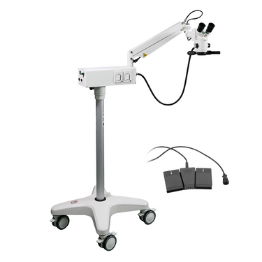
5.3X/8X/12X Halogen Coaxial Reflection Light Pneumatic Arm Floor Stand Binocular Parallel Multiple Power Surgical Microscope (Foot Control: Focus) SM51050192

SKU:
SM51050192
Warranty:
5/1 Years
Certificate:
ISO13485, RoHS, CE
Condition:
New
  • 5.3X/8X/12X Halogen Coaxial Reflection Light Pneumatic Arm Floor Stand Binocular Parallel Multiple Power Surgical Microscope (Foot Control: Focus) SM51050192
  • 5.3X/8X/12X Halogen Coaxial Reflection Light Pneumatic Arm Floor Stand Binocular Parallel Multiple Power Surgical Microscope (Foot Control: Focus) SM51050192
  • 5.3X/8X/12X Halogen Coaxial Reflection Light Pneumatic Arm Floor Stand Binocular Parallel Multiple Power Surgical Microscope (Foot Control: Focus) SM51050192
  • 5.3X/8X/12X Halogen Coaxial Reflection Light Pneumatic Arm Floor Stand Binocular Parallel Multiple Power Surgical Microscope (Foot Control: Focus) SM51050192
  • 5.3X/8X/12X Halogen Coaxial Reflection Light Pneumatic Arm Floor Stand Binocular Parallel Multiple Power Surgical Microscope (Foot Control: Focus) SM51050192
  • 5.3X/8X/12X Halogen Coaxial Reflection Light Pneumatic Arm Floor Stand Binocular Parallel Multiple Power Surgical Microscope (Foot Control: Focus) SM51050192
  • 5.3X/8X/12X Halogen Coaxial Reflection Light Pneumatic Arm Floor Stand Binocular Parallel Multiple Power Surgical Microscope (Foot Control: Focus) SM51050192
  • 5.3X/8X/12X Halogen Coaxial Reflection Light Pneumatic Arm Floor Stand Binocular Parallel Multiple Power Surgical Microscope (Foot Control: Focus) SM51050192
  • 5.3X/8X/12X Halogen Coaxial Reflection Light Pneumatic Arm Floor Stand Binocular Parallel Multiple Power Surgical Microscope (Foot Control: Focus) SM51050192
  • 5.3X/8X/12X Halogen Coaxial Reflection Light Pneumatic Arm Floor Stand Binocular Parallel Multiple Power Surgical Microscope (Foot Control: Focus) SM51050192
  • 5.3X/8X/12X Halogen Coaxial Reflection Light Pneumatic Arm Floor Stand Binocular Parallel Multiple Power Surgical Microscope (Foot Control: Focus) SM51050192
  • 5.3X/8X/12X Halogen Coaxial Reflection Light Pneumatic Arm Floor Stand Binocular Parallel Multiple Power Surgical Microscope (Foot Control: Focus) SM51050192
  • 5.3X/8X/12X Halogen Coaxial Reflection Light Pneumatic Arm Floor Stand Binocular Parallel Multiple Power Surgical Microscope (Foot Control: Focus) SM51050192
  • 5.3X/8X/12X Halogen Coaxial Reflection Light Pneumatic Arm Floor Stand Binocular Parallel Multiple Power Surgical Microscope (Foot Control: Focus) SM51050192
  • 5.3X/8X/12X Halogen Coaxial Reflection Light Pneumatic Arm Floor Stand Binocular Parallel Multiple Power Surgical Microscope (Foot Control: Focus) SM51050192
  • 5.3X/8X/12X Halogen Coaxial Reflection Light Pneumatic Arm Floor Stand Binocular Parallel Multiple Power Surgical Microscope (Foot Control: Focus) SM51050192
  • 5.3X/8X/12X Halogen Coaxial Reflection Light Pneumatic Arm Floor Stand Binocular Parallel Multiple Power Surgical Microscope (Foot Control: Focus) SM51050192
$6,317.98
& Free shipping * Contiguous USA Only
Pre-Order. Place your order and we’ll email you once we have an estimated delivery date.
Other Shipping Options
Quick Overview
Infinite. Total Magnification: 5.3X/8X/12X. 12.5X Adjustable Eyepiece. f200 Infinity Achromatic Objective. Binocular. Eye Tube Angle: 45°. Eyepiece Field of View: Dia. 16mm. Pneumatic Arm. Total Arm Length: 980mm. Focus Motorized. Illumination Type: Halogen Coaxial Reflection Light. Flexible Pipe Light. Input Voltage: AC 115/230V 50/60HZ.


SM51050192 Floor Stand Binocular Parallel Multiple Power Surgical Microscope (Foot Control: Focus)
Optical System Specifications
Optical SystemInfinite
System Optical Magnification5.3X/8X/12X
Total Magnification5.3X/8X/12X
Standard Eyepiece12.5X Adjustable Eyepiece
Standard Objectivef200 Infinity Achromatic Objective
System Field of View Dia. 16.7mm/ Dia. 25mm/ Dia. 37mm
System Working Distance190mm
Binocular Multiple Power Body
Body Optical SystemInfinite
Body Magnification0.64X/1X/1.5X
Observation MethodBinocular
Body Mount Type for Eye TubeFastening Screw
Body Mounting Size for Eye Tube Dia. 50mm
Eye Tube Adjustment ModeSiedentopf
Eye Tube Angle45°
Erect/Inverted ImageErect image
Interpupillary Adjustment55-75mm
Eyepiece TypeAdjustable Eyepiece
Eyepiece Optical Magnification12.5X
Eyepiece Field of View Dia. 16mm
Eyepoint TypeHigh Eyepoint Eyepiece
Eye Guard InstallationFixed Eye Guard
Eye Guard MaterialRubber
Eye Guard Mount Size Dia. 36mm
Stereo Objective
Objective Optical SystemInfinite
Objective Optical Magnification0.64X
Objective TypePlan Apochromatic Objective
Objective Focal Length200mm
Objective Working Distance190mm
Objective Outer Diameter Dia. 59mm
Flexible Arm
Stand TypePneumatic Arm
Vertical Post Height836mm
Vertical Post Diameter Dia. 54mm
Horizontal Arm TypeHorizontal Post
Horizontal Arm Length400mm
Total Arm Length980mm
Horizontal Rotation Angle330° Degree Rotatable
Base TypeCross-shaped Wheeled Base with Lockable Casters
Base ShapeCross-bonding
Base Mounting Size Dia. 54mm
Base Dimensions Dia. 68x21cm
Focus ModeMotorized/Manual
Fine Focus Travel Distance30mm
Illumination TypeHalogen Coaxial Reflection Light
Electrical Control
Electric ControllerFocus Motorized
Controller Operation TypeFoot Control
Optical Fiber Light Guide
Optical Fiber Cable TypeFlexible Pipe Light
Fiber Light Output Port Size Dia. 6.5mm
Fiber Cable Output Port Adapter Size Dia. 9mm
Fiber Light Input Port Size Dia. 6.5mm
Fiber Cable Input Port Adapter Size Dia. 9mm
Pipe MaterialFlexible Fiber Cable
Optical Fiber Cable Length940mm
Pipe ColorBlack
Power Supply
Output Power100W
Input VoltageAC 115/230V 50/60HZ
Output VoltageDC 12V
Power Cord Connector TypeUSA 3 Pins
Power Cable Length3m
Other Parameters
Surface TreatmentSpray Paint
MaterialMetal
ColorWhite
Net Weight41kg (90.4lbs)
Series
SM5105SM51050192


Technical Info

Instructions
Surgical MicroscopeClose Λ
Surgical microscope is a stereo microscope used for microsurgery, diagnostic treatment, observation, and research and other different functions of humans and animals under the microscope.

An surgical microscope has an optical system for observation, including an eyepiece, an objective lens, an objective lens zoom set, and lighting, stands, and electrical components, and its accessories are configured according to different needs.
The magnification of the surgical microscope is generally 8-20X. Compared with the stereo microscope, it has special requirements of large field of view, large depth of field, and long working distance, characterized by compact structure, small size and flexible operation.
Surgical microscope typically has flexible, large-space moving stands and electric controls.

For more precautions for use of surgical microscope, please refer to the Stereo Microscope on the BoliOptics website.
InfiniteClose Λ
Microscopes and components have two types of optical path design structures.
One type is finite optical structural design, in which light passing through the objective lens is directed at the intermediate image plane (located in the front focal plane of the eyepiece) and converges at that point. The finite structure is an integrated design, with a compact structure, and it is a kind of economical microscope.
Another type is infinite optical structural design, in which the light between the tube lens after passing the objective lens becomes "parallel light". Within this distance, various kinds of optical components necessary such as beam splitters or optical filters call be added, and at the same time, this kind of design has better imaging results. As the design is modular, it is also called modular microscope. The modular structure facilitates the addition of different imaging and lighting accessories in the middle of the system as required.
The main components of infinite and finite, especially objective lens, are usually not interchangeable for use, and even if they can be imaged, the image quality will also have some defects.

The separative two-objective lens structure of the dual-light path of stereo microscope (SZ/FS microscope) is also known as Greenough.
Parallel optical microscope uses a parallel structure (PZ microscope), which is different from the separative two-object lens structure, and because its objective lens is one and the same, it is therefore also known as the CMO common main objective.
System Optical MagnificationClose Λ
The magnification of the objective lens refers to the lateral magnification, it is the ratio of the image to the real size after the original image is magnified by the instrument. This multiple refers to the length or width of the magnified object.
System optical magnification is the product of the eyepiece and the objective lens (objective lens zoom set) of the optical imaging part within the system.
Optical magnification = eyepiece multiple X objective lens/objective lens set

The maximum optical magnification of the microscope depends on the wavelength of the light to which the object is illuminated. The size of the object that can be observed must be greater than the wavelength of the light. Otherwise, the light cannot be reflected or transmitted, or recognized by the human eye. The shortest wavelength of ultraviolet light is 0.2 microns, so the resolution of the optical microscope in the visible range does not exceed 0.2 microns, or 200 nanometers. This size is converted to the magnification of the microscope, and it is the optical magnification of 2000X. Usually, the compound microscope can achieve 100X objective lens, the eyepiece is 20X, and the magnification can reach 2000X. If it is bigger, it will be called "invalid magnification", that is, the image is large, but the resolution is no longer increased, and no more details and information can be seen.
Total MagnificationClose Λ
Total magnification is the magnification of the observed object finally obtained by the instrument. This magnification is often the product of the optical magnification and the electronic magnification.
When it is only optically magnified, the total magnification will be the optical magnification.

Total magnification = optical magnification X electronic magnification
Total magnification = (objective X photo eyepiece) X (display size / camera sensor target )
System Field of ViewClose Λ
Field of View, is also called FOV.
The field of view, or FOV, refers to the size of the object plane (i.e., the plane of the point of the observed object perpendicular to the optical axis), or of its conjugate plane (i.e., object to primary image distance), represented by a line value.
System field of view is the size of the actual diameter of the image of the terminal display device of the instrument, such as the size of the image in the eyepiece or in the display.

Field of view number refers to the diameter of the field diaphragm of the objective lens, or the diameter of the image plane formed by the field diaphragm.
Field of view number of objective lens = field of view number of eyepiece / (objective magnification / mechanical tube length)

Large field of view makes it easy to observe the full view and more range of the observed object, but the field of view (FOV) is inversely proportional to the magnification and inversely proportional to the resolution, that is, the larger the field of view, the smaller the magnification, and also the lower the resolution of the object to be observed.
There are usually two ways to increase the field of view, one is to replace with an objective lens of a smaller multiple, or to replace with an eyepiece of a smaller multiple.
System Working DistanceClose Λ
Working distance, also referred to as WD, is usually the vertical distance from the foremost surface end of the objective lens of the microscope to the surface of the observed object.
When the working distance or WD is large, the space between the objective lens and the object to be observed is also large, which can facilitate operation and the use of corresponding lighting conditions.
In general, system working distance is the working distance of the objective lens. When some other equipment, such as a light source etc., is used below the objective lens, the working distance (i.e., space) will become smaller.

Working distance or WD is related to the design of the working distance of the objective lens. Generally speaking, the bigger the magnification of the objective lens, the smaller the working distance. Conversely, the smaller the magnification of the objective lens, the greater the working distance.
When it is necessary to change the working distance requirement, it can be realized by changing the magnification of the objective lens.
Binocular Multiple Power BodyClose Λ
Binocular multiple power body refers to that the objective lens of the stereo microscope has a set multiple of more than two, and when multiple-shifting is performed, a multiple different magnifications can be obtained.
When the body needs other different magnifications, it can also be solved by adding or changing the objective lens/auxiliary objective lens, or by changing the eyepieces of different multiples.
SiedentopfClose Λ
For siedentopf eyetube, when changing the interpupillary distance, it requires two hands pushing or pulling the two eyetubes left and right simultaneously, and the two eyepiece tubes or eyetubes will change their position at the same time.
Eye Tube AngleClose Λ
Usually the Microscope Eyetube is 45°, some is 30°, Tiltable Eyetube Angle design of a microscope is also known as the ergonomics microscope.
0-30° or 0-45° is an ergonomic design. When the mechanical tube length / focal length of the tube of the microscope is relatively big, the microscope is relatively high, and the user's height or the seat of the work desk is not suitable, long-term use of microscope may cause sitting discomfort.
Eyepiece tube with variable angle can freely adjust the angle without lowering the head. Especially when it is close to 0 degree and the human eye is close to horizontal viewing, long-time or long-term use can avoid fatigue damage to the cervical vertebra.
Erect/Inverted ImageClose Λ
After imaging through a set of objective lenses, the object observed and the image seen by the human eye is inverted. When the observed object is manipulated, move the specimen or object, the image will move in the opposite direction in the field of view. Most of the biological microscopes are reversed-phase designs.
When needing to operate works with accurate direction, it is necessary to design it into a forward microscope. Generally stereo microscopes and metallurgical microscopes are all of erect image design.
When observing through the camera and display, the erect and inverted image can be changed by the orientation of the camera.
Interpupillary AdjustmentClose Λ
The distance between the two pupils of the human eye is different. When the image of exit pupil of the two eyepieces of the microscope are not aligned with the entry pupil of the eye, the two eyes will see different images, which can cause discomfort.
Adjust the distance between the two eyepieces, to accommodate or adapt to the pupil distance of the observer's eyes. The adjustment range is generally between 55-75mm.
Adjustable EyepieceClose Λ
The adjustable eyepiece is between the lens of the eyepiece and the focal plane, with distance adjustable device.
For most people, their two eyes, the left and the right, have different vision. For adjustable eyepieces, the eyepoint height of the eyepiece can be adjusted to compensate for the difference in vision between the two eyes, making the image in the two eyes clear and consistent.
The range of adjustment of the general eyepiece is that the diopter is plus or minus 5 degrees, and the maximum difference between the two eyepieces can reach 10 degrees. Before use, it is generally necessary to adjust both eyepieces to the initial position where the scale is displayed as 0, which is used as a baseline to facilitate up and down adjustment.
The reticle position of the eyepiece is generally 10mm below the fixed position of the eyepiece tube. Because the vision of each person is different, some people may not be able to see the reticle clearly. For adjustable eyepiece, the height of the reticle position can be adjusted to make the reticle and the observed object clear at the same time, this is the advantage of adjustable eyepiece that mounts the diopter adjustment on the eyepiece tube compared with non-adjustable eyepiece.
When non-adjustable eyepiece is equipped with a reticle, if the diopter is adjusted, the reticle will rotate accordingly, thereby affecting the position of the measurement. For adjustable eyepiece, when its diopter is adjusted, its reticle does not rotate.

Eyepiece Optical MagnificationClose Λ
Eyepiece optical magnification is the visual magnification of the virtual image after initial imaging through the eyepiece. When the human eye observes through the eyepiece, the ratio of the tangent of the angle of view of the image and the tangent of the angle of view of the human eye when viewing or observing the object directly at the reference viewing distance is usually calculated according to 250 mm/focal length of eyepiece.
The standard configuration of a general microscope is a 10X eyepiece.
Usually, the magnification of the eyepiece of compound microscope is 5X, 8X, 10X, 12.5X, 16X, 20X.
As stereo microscope has a low total magnification, its eyepiece magnification generally does not use 5X, but can achieve 25X, 30X and other much bigger magnification.
Eyepiece Field of ViewClose Λ
The eyepiece field of view is the diameter of the field diaphragm of the eyepiece, or the diameter of the image plane of the field diaphragm imaged by the field diaphragm.
The diameter of a large field of view can increase the viewing range, and see more detail in the field of view. However, if the field of view is too large, the spherical aberration and distortion around the eyepiece will increase, and the stray light around the field of view will affect the imaging effect.
Eyepoint TypeClose Λ
Eye point refers to the axial distance between the upper end of the metal frame of the eyepiece and the exit of pupil.
The exit of pupil distance of high eyepoint eyepiece is farther than that of the eye lens of the ordinary eyepiece. When this distance is greater than or equal to 18mm, it is a high eyepoint eyepiece. When observing, one does not need to be too close to the eyepiece lens, making it comfort to observe, and it can also be viewed with glasses. Generally, there is a glasses logo on the eyepiece, indicating that it is a high eyepoint eyepiece.
Fixed Eye GuardClose Λ
Eye guard installation refers to that the eye guard has been installed on the eyepiece in advance as a component.
Objective Optical MagnificationClose Λ
The finite objective is the lateral magnification of the primary image formed by the objective at a prescribed distance.

Infinite objective is the lateral magnification of the real image produced by the combination of the objective and the tube lens.
Infinite objective magnification = tube lens focal length (mm) / objective focal length (mm)

Lateral magnification of the image, that is, the ratio of the size of the image to the size of the object.
The larger the magnification of the objective, the higher the resolution, the smaller the corresponding field of view, and the shorter the working distance.
Objective TypeClose Λ
In the case of polychromatic light imaging, the aberration caused by the light of different wavelengths becomes chromatic aberration. Achromatic aberration is to correct the axial chromatic aberration to the two line spectra (C line, F line); apochromatic aberration is to correct the three line spectra (C line, D line, F line).
The objective is designed according to the achromaticity and the flatness of the field of view. It can be divided into the following categories.

Achromatic objective: achromatic objective has corrected the chromatic aberration, spherical aberration, and comatic aberration. The chromatic portion of the achromatic objective has corrected only red and green, so when using achromatic objective, yellow-green filters are often used to reduce aberrations. The aberration of the achromatic objective in the center of the field of view is basically corrected, and as its structure is simple, the cost is low, it is commonly used in a microscope.

Semi-plan achromatic objective: in addition to meeting the requirements of achromatic objective, the curvature of field and astigmatism of the objective should also be properly corrected.
Plan achromatic objective: in addition to meeting the requirements of achromatic objectives, the curvature of field and astigmatism of the objective should also be well corrected. The plan objective provides a very good correction of the image plane curvature in the field of view of the objective, making the entire field of view smooth and easy to observe, especially in measurement it has achieved a more accurate effect.

Plan semi-apochromatic objective: in addition to meeting the requirements of plan achromatic objective, it is necessary to well correct the secondary spectrum of the objective (the axial chromatic aberration of the C line and the F line).
Plan apochromatic objective: in addition to meeting the requirements of plan achromatic objective, it is necessary to very well correct the tertiary spectrum of the objective (the axial chromatic aberration of the C line, the D line and the F line) and spherochromatic aberration. The apochromatic aberration has corrected the chromatic aberration in the range of red, green and purple (basically the entire visible light), and there is basically no limitation on the imaging effect of the light source. Generally, the apochromatic aberration is used in a high magnification objective.

Objective Working DistanceClose Λ
The objective working distance is the vertical distance from the foremost surface end of the objective of the microscope to the object surface to be observed.
Generally, the greater the magnification, the higher the resolution of the objective, and the smaller the working distance, the smaller the field of view. Conversely, the smaller the magnification, the lower the resolution of the objective, and the greater the working distance, and greater the field of view.
High-magnification objectives (such as 80X and 100X objectives) have a very short working distance. Be very careful when focusing for observation. Generally, it is after the objective is in position, the axial limit protection is locked, then the objective is moved away from the direction of the observed object.
The relatively greater working distance leaves a relatively large space between the objective and the object to be observed. It is suitable for under microscope operation, and it is also easier to use more illumination methods. The defect is that it may reduce the numerical aperture of the objective, thereby reducing the resolution.
Flexible ArmClose Λ
Flexible arm is an arm or stand that imitates the human arm. It is a combination of several mechanical arm joints to complete the horizontal and vertical movement and freely adjust the focus position of the microscope. Flexible arm allows the microscope to move flexibly and freely over a wide range, and is also suitable for viewing larger objects.
The fixing method of the arm is usually optional, with strong interchangeability. Below the observation of the microscope there is an empty workbench, which can be used to place various kinds of platforms, work operating tables, tools, etc., and can be freely combined into different working positions.
In industrial places, most of the working positions are fixed. Sometimes, a lot of tools, equipment and instruments need to be placed in one working position. Because the microscope is relatively large in size and takes up also a relatively bigger space, and not convenient to move back and forth, therefore the flexible arm can be placed in a flexible position, and does not occupy the most commonly used workbench. When in use, the microscope can be moved over, and pushed to the side when not in use. This is very suitable for use in electronics factories, installation and maintenance, medical and animal anatomy, archaeology and other industries.
Flexible arm generally does not have a fixed focusing device, and you can choose a variety of flexible accessories.
When adjusting the height of the flexible arm, you need to use both hands at the same time, with one hand holding the microscope or the forearm of the stand, and the other adjusting the adjusting screw or spring mechanism that looses/tightens the arm. When releasing, pay attention to avoiding sudden sliding down.

Because one needs to ensure the flexibility of the arm or stand, there are many locking buttons in all directions. After the necessary locking buttons are adjusted, it must be ensured that each knob is in locked state to avoid sliding, tilting, and flipping of the microscope, thereby damaging the microscope and the items on the workbench.

Flexible arm has a mechanism of the hydraulic spring for adjusting the pre-tightening tension. When different microscopes weigh differently, these flexible arms can be adjusted to make the microscope more stable.
Electrical ControlClose Λ
Electric/CNC platform refers to the movement mode operated and controlled by motor or digital signal during the XY or Z-axis focusing of the microscope and the movement of the platform.
Optical Fiber Light GuideClose Λ
Optical fiber bundle for illumination, is referred to as optical fiber light guide for short.
Optical fiber light guide is a fiber core made of transparent material (typically, glass fiber is made of silicon dioxide). Around the fiber core, a cladding layer is formed, using a material having a refractive index lower than that of the fiber core, that is, if the refractive index of the fiber core and the cladding layer are n1 and n2, then n1 must be >n2. The transmission of the optical fiber makes use of the principle of total reflection of light. In this fiber core medium, light is to maintain its characteristics of optical waveform for transmission, wherein the fiber core portion of high refractive index is the main channel for light transmission, while the outer casing of low refractive index covers the entire fiber core. Since the core has a higher refractive index than the outer casing, total reflection occurs, and therefore light can be transmitted in the fiber core.

The core of the optical fiber is generally classified into glass fiber, quartz fiber, plastic fiber, and liquid core fiber etc.
Microscope illumination usually uses glass fiber, which can have better transmittance for light of different wavelengths. For glass fiber, its optical core material is multi-component optical glass with high refractive index, whereas its cladding material is optical glass with low refractive index. The commonly used multi-component glass formula include: sodium-borosilicate glass (Na-B-Si), potassium-borosilicate glass (K-B-Si), sodium-zinc aluminoborosilicate glass (Na-Zn-Al-B-Si), and the like.
Glass fiber, made of optical glass, has a much higher transparency than a ordinary set of glass, but still has a relatively high attenuation value, generally about 1dB/m.
The lighting fiber optic wire is very thin, and cannot be bent at a large angle. Generally, its minimum bending radius ≥30D (Min. bending radius ≥30D). Check the breaking of the fiber optic wire, you can use one side section to face the light, and the other side section to see the dark part. If there is too much break, it can’t be repaired, but the entire fiber be replaced.
PackagingClose Λ
After unpacking, carefully inspect the various random accessories and parts in the package to avoid omissions. In order to save space and ensure safety of components, some components will be placed outside the inner packaging box, so be careful of their inspection.
For special packaging, it is generally after opening the box, all packaging boxes, protective foam, plastic bags should be kept for a period of time. If there is a problem during the return period, you can return or exchange the original. After the return period (usually 10-30 days, according to the manufacturer’s Instruction of Terms of Service), these packaging boxes may be disposed of if there is no problem.


Optical Data


Microscope Optical Data Sheet
P/NObjectiveObjective Working DistanceEyepiece
SM51050192   (12.5X  Dia. 16mm)
MagnificationField of View(mm)
SM510501920.64X190mm8X25mm
1. Magnification=Objective Optical Magnification * Body Magnification * Eyepiece Optical Magnification
2. Field of View=Eyepiece Field of View /(Objective Optical Magnification*Body Magnification)
3. The Darker background items are Standard items, the white background items are optional items.

More Info

Contains  
Parts Including
Screw Model and QuantityM10x30mm 1pc
Allen KeyM8 1pc M6 1pc M3 1pc
Spare Bulb1pc
Product Instructions/Operation Manual1pc
Packing  
Packaging TypeCarton Packaging
Packaging MaterialCorrugated Carton
Packaging Dimensions(1)79x61x48cm (31x24x19″)
Inner Packing MaterialPlastic Bag
Ancillary Packaging MaterialsStyrofoam
Gross Weight51.5kg (113.5lbs)
Minimum Packaging Quantity1pc
Transportation CartonCarton Packaging
Transportation Carton MaterialCorrugated Carton
Transportation Carton Dimensions(1)81x63x51cm (32x25x20″)
Total Gross Weight of Transportation(kilogram)51.5
Total Gross Weight of Transportation(pound)113.5
Quantity of One Transportation Carton1pc

Related Products